Space environment applications
The Space environment applications cover a wide range of modelling problems arising when a spacecraft evolves in Space.
Several specialized applications are available such as Atomox, Perturbations, Dosrad, Debris, Outgassing, Plume, and GTD, each of them tailored to address critical aspects of the space environment.
Each application is bundled with the Systema framework and is available for individual use. Alternatively, an “environment package” is available which includes 4 of these applications with the Systema framework: Atomox, Perturbations, Dosrad and Debris.
Atomox
During space missions in the low-Earth orbit regime, below 1000 km altitude, a good understanding of temperature, total density, concentrations of gas constituents, and pressure is crucial.
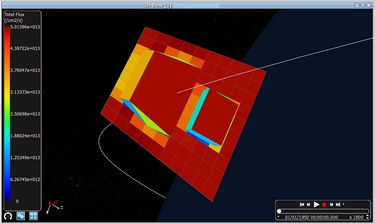
Atomox is an enhanced 3D numerical analysis tool designed for the evaluation of atomic oxygen (and other atmospheric species) flux, fluence, and material erosion based on existing atmosphere and wind models. It involves mission and pointing modules, along with ray-tracing technique and 2D /3D visualisation facilities.
All spacecraft surfaces are meshed into elements, and analyses are conducted individually on each element. The mission and pointing modules provide discretized location of the spacecraft together with its velocity with respect to the Earth. At the end of each orbital arc, Atomox computes orbital-averaged or accumulated values that can be extrapolated over several arcs, if specified.
The ray-tracing technique (Monte-Carlo technique) is used. It considers emitted rays from the surface of the satellite and detects if a given element is struck by the ray. Then, the ray can be followed by multiple reflections on the satellite surfaces (specular and diffuse reflectance taken into account).
Outputs include:
- Total impacting flux and fluence
- Absorbed flux and fluence
- Direct impacting flux and fluence
- Spacecraft material erosion
- Mean impact velocity (amplitude and direction)
- Mean particle energy
The model incorporates the effects of thermal motion of ambient particles in conjunction with ambient atmospheric density and spacecraft velocity. This enables accurate modelling of erosion effects, caused by thermal molecular motion, even on shadowed surfaces, providing essential data for high-fidelity spacecraft modelling and material durability assessments during the mission.
Perturbations
Perturbations is a Systema application that delivers analysis of environmental perturbations caused by solar pressure and air drag generated by atmosphere remains at low altitudes. It plays a key role in the spacecraft analysis process by modelling external forces acting on the spacecraft throughout its mission.
Solar pressure
The solar pressure module computes the force generated by incident sunlight photons impacting spacecraft surfaces. Solar radiation pressure is defined as the vector difference between the incident and reflected momentum flux.
Sun radiation incident on the satellite's surfaces produces a radiation pressure, or force per unit area, equal to the vector difference between the incident and reflected momentum flux.
The major factors determining the radiation pressure are:
- The intensity, spectral and spatial distribution of solar radiation
- The geometry of the satellite
- The optical properties of the satellite surfaces
Solar pressure allows to account for the induced forces and torques using a state-of-the-art analytical ray tracing algorithm. This enables precise evaluation of spacecraft dynamic response to solar influence under various mission conditions.
Air drag
In low-Earth orbit, a satellite moves through the residual atmosphere and experiences aerodynamic forces. These forces result from the interaction of the atmosphere molecules with the satellite's surfaces.
The air drag module computes perturbing forces, torques and thermal fluxes resulting from the interaction of the atmosphere particles with the satellite's surfaces.
Air drag depends on several key parameters:
- The satellite velocity
- The atmospheric constituents, their density and their kinetic temperature
- The motion of the atmosphere
- The geometry of the satellite
- The orientation of the satellite w.r.t. the incoming flow
- The surface characteristics and temperature
This force is usually modelled by assuming that it acts in a direction opposite to the spacecraft's velocity vector relative to the ambient atmosphere. The results are computed using a modified Maxellian model for Particle/Wall Interaction. This tool enhances scenario specification, supports accurate simulation of perturbing forces, and helps engineers anticipate design impacts early in the mission planning phase.
Dosrad
Dosrad computes the radiation dose received by electronic components or materials when exposed to the space environment. It performs dose integration using an efficient solid-angle sectoring analysis that supports detailed simulation and engineering assessment.
Using a powerful ray-tracing algorithm, Dosrad traces rays from a dose evaluation point outward through the spacecraft. For each ray, the amount of shielding encountered is calculated based on material densities. This data is used to generate a dose-depth curve and calculate the weighted dose contribution. The results provide average doses per mesh and per face.
Dosrad supports thickness and volume computations for surface elements, allowing for detailed evaluations of: equipment dose/shielding, component dose, dose mapping, advanced features, honeycomb management, rays display.
Dosrad functionalities include:
- Analysis at equipment and component level
- Dose and shielding (protective thickness) computation
- SLANT and NORM computation
- Computation of satellite equivalent thickness for sub specification (SLANT FOR SUB)
- Manage real volume or shell with thickness
- Detailed honeycomb modelling
- Efficient ray-tracing algorithm to compute ray paths in a 3D model
- Computation of all targets / bounding box thickness in one run
Dosrad performs computations of:
- Dose on a point / dose received by a component
- Dose / shielding on a bounding box of an equipment
- Dose cartography / mapping computation allowing to have a mean dose on a surface (electronic card, optics, detector…)
These advanced capabilities contribute to high-fidelity spacecraft modelling, ensuring mission reliability through robust shielding analysis and radiation impact prediction.
Debris
Debris is a Systema application designed to predict the risk of spacecraft equipment or structural failure due to space debris. With the continuous growth of orbital debris, the potential for mission-critical damage increases, driving the need for numerical tools to support MMOD (MicroMeteoroid and Orbital Debris) risk assessment methodologies.
Larger on-orbit objects are tracked, and orbit change manoeuvres can be performed to avoid potential collisions. However, for non-trackable debris, spacecraft must rely on shielding or other risk mitigation strategies to minimise the chances of impact. To support the spacecraft design and analysis process, Debris offers engineers a reliable tool to model and assess the risk of impact and inform protective design decisions.
The prevention of critical damage to sensitive surfaces, which could compromise mission objectives and spacecraft lifetime, is a growing concern among satellite design engineers. To optimise the positioning of critical elements and maximise overall performance efficiency, it is essential to have a comprehensive understanding and quantitative characterisation of MMOD impact risk.
Debris is designed to provide engineers with a practical tool for evaluating the probability of no-penetration (PNP) of selected elements within the spacecraft geometry. The simulation process is engineered to be compatible with repeated trade-off analysis between different spacecraft configurations.
MMOD risk assessment via Debris includes:
- Computation of the number of direct impacts on an element
- Computation of the number of penetrations on an element
- Computation of damaged area on an element
- Computation of the PNP of an element
These features support engineering decisions and ensure spacecraft modelling accounts for structural vulnerabilities and debris exposure in a quantifiable way.
Material contamination - Outgassing
Outgassing is a Systema application that evaluates the deposit of contaminants on the spacecraft surfaces, such as mirrors and thermal coatings, caused by outgassed materials in vacuum conditions. The software simulates the deposit of contaminants over time, which is critical for accurate surface performance prediction during missions.
The contamination modelling process proceeds in two main steps:
- The computation of the mass transfer factors between surfaces using Monte-Carlo method and the time integration of the deposit.
- Computation of the direct mass transfer is done via:
- An advanced ray-tracing solver:
- Multi-threaded computation
- Using management of all the shell shapes including boolean shapes
- Allowing the display of mass transfer factors on the 3D models
- Allowing the display of rays contributing to the mass transfer factors
- Computation of the deposits is done :
- With multi-threading computation (by species) of the deposits computation
- Allowing the display of deposit and remaining mass to be outgassed on the 3D model as function of time
- An advanced ray-tracing solver:
This application enhances simulation accuracy and provides essential inputs to the spacecraft design and analysis process by ensuring effective contamination control through visualisation and modelling displaying deposition patterns and residual outgassed mass over time.
Plume suite: Plumflow
Plumflow is a module included in the Systema-Plume suite that computes the flow field generated by thrusters operating in a vacuum. It models a wide range of plume characteristics, including:
- Chemical composition of the gas in the chamber and in the plume
- Physical properties of the gas: viscosity, heat capacity, g, species diameter
- If necessary, description of the non-gaseous phase : particles or droplets
- Properties of the plume along the streamlines (velocity, density, pressures…)
- Characteristics of the engine (thrust, mass flow rate…)
The software applies multiple advanced methods:
- This calculation involves a large panel of different methods:
- The computation of the chemical composition and physical properties is performed under assumption of thermodynamic equilibrium
- The computation of the flow inside the engine and its expansion in the surrounding space uses the method of characteristics or navier-stokes equation resolution. These programs perform the simulation of the boundary layer expansion at the nozzle lip
- The extension of the flow-field beyond the navier-stokes and the method of characteristics computational domain uses the source-flow method, considering the expansion as isotropic
- Other methods can be used to handle more specific problems like direct simulation Monte-Carlo at the nozzle lip or droplets propagation
These capabilities enable comprehensive simulation of thruster behaviour and plume evolution under space conditions, contributing to accurate spacecraft modelling and engineering analyses.
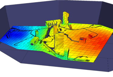
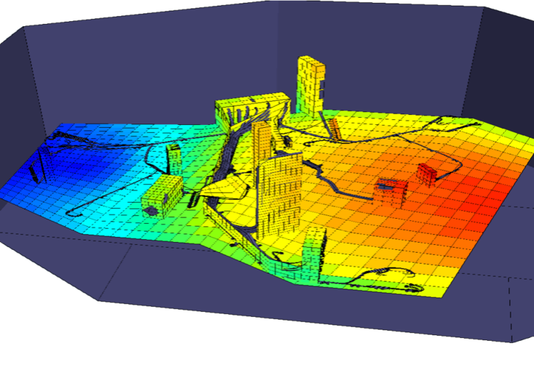
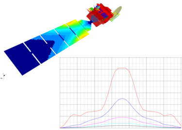
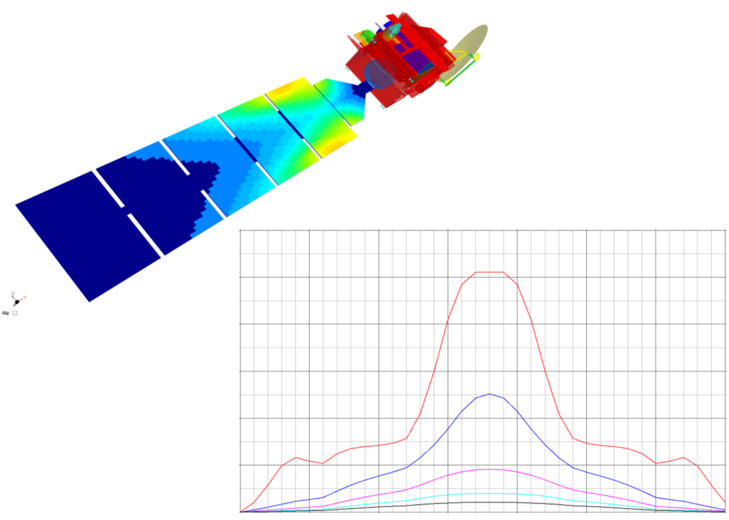
The image below shows the pressure distribution on the solar array of an observation satellite alongside the thruster flow field in vacuum.
Plume Suite: Plumimp
Plumimp is the second module included in the Systema-Plume suite dedicated to modelling the interaction between spacecraft and chemical thruster plumes in space. Plumimp analyses the impact of plume impingement on spacecraft surfaces. Plumflow and Plumimp are delivered as a unified package, providing engineers with a comprehensive and validated engineering simulation tool to assess dynamic, thermal, and contamination effects.
The main perturbing effects due to the impoundment of thrusters plumes are numerous:
- Perturbing forces and torques due to the plume impingement on the spacecraft surfaces
- Heat convective flux due to the impingement of the gas and radiative flux due to the particles
- Modification of the surfaces properties due to the contaminants deposit
- Effects of the contaminants cloud on the optical devices (absorption, emission, scattering)
- Induced pressure at instrument / equipment level
Plumimp allows the modelling of such effects using an analytical ray-tracing technique. Rays are traced from the thruster of interest to all the meshes of the geometry. Each ray provides information regarding the current mesh and the thruster: incidence angle, distance to the thruster, etc... If another surface is encountered, the current mesh is said to be shadowed. Otherwise, the impact parameters as well as the derivative quantities are computed, cumulated (on meshes, on surfaces and possibly on groups) and stored in the corresponding file: in the Impingement information file for the impact parameters and in the derivative quantities file for the other quantities.
This approach ensures accurate result visualisation and high-fidelity spacecraft modelling, enabling performance optimisation and early detection of contamination or disturbance risks during spacecraft configuration.
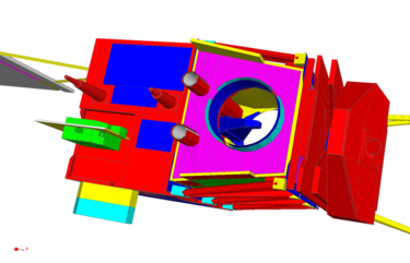
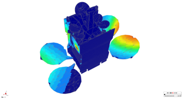
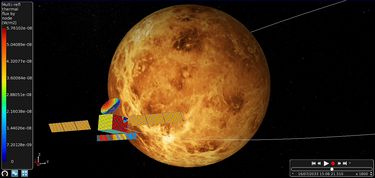
The image below shows thermal fluxes computed on a complete telecom satellite model.
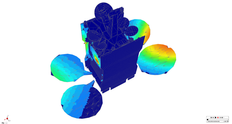
Radio-frequency GTD
GTD is a Systema application dedicated to radio-frequency (RF) analysis based on the geometrical theory of diffraction (GTD). It plays a crucial role in the spacecraft design and analysis process by modelling antenna behaviour and interactions within complex satellite structures.
The radio frequency (RF) analysis of satellites is an essential step to ensure a successful mission. For directive antennae, the satellite structure and nearby payloads may often be neglected, but for low-gain and omnidirectional antennae, the structure can substantially influence radiation characteristics.
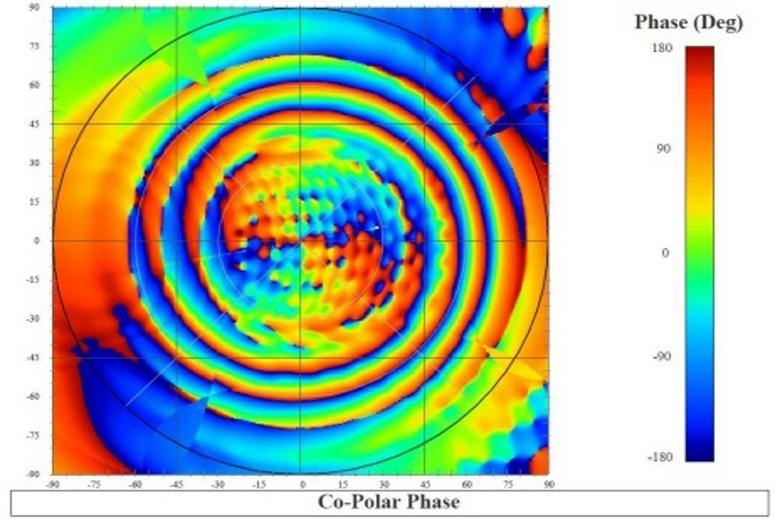
For these types of antennae, it is critical to compute the interfered antenna pattern when mounted on a satellite structure. GTD provides this capability, enhancing the accuracy of simulation and antenna design.
In addition to the antenna pattern, this software enables the calculation of antenna-to-antenna coupling due to structural effects, which is important for optimal antenna positioning and electromagnetic compatibility (EMC) analysis. It also allows field computation on physical and virtual spacecraft surfaces.
The RF analysis is based on GTD, which assumes high-frequency wave behaviour. Ray tracing is performed in two modes:
- Backward ray tracing: calculates ray paths from the observation point, using known source position and geometry
- Forward ray tracing: emits rays from the source in all directions and tracks their full propagation
The software supports:
- Multiple reflected and diffracted rays per surface (up to two per ray)
- Curved and planar surface analysis
- Creeping ray effects on planar surfaces
For antenna coupling, GTD determines:
- Coupling ray paths using ray tracing which determines the coupling ray paths
- Coupling value calculated by field propagation along the rays using a complex or RSS field summation
GTD helps engineers with result visualisation, RF System analysis such as early interaction issue detection, antenna placement optimisation, and antenna pattern prediction. It is a valuable tool for designing high-performance communication systems under realistic space mission constraints.
